PML Banner
black line
 Data Analysis Sheet L.2

Data analysis sheet for in-plane length measurements when the transitional edges
defining L are oriented in the same direction (or for an inside edge-to-outside edge length
measurement from one data trace)
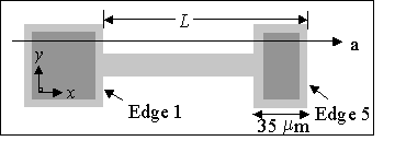
Top view of a fixed-fixed beam test structure depicting the measurement to be made.

Figure L.2.1.  Top view of a fixed-fixed beam test structure depicting the measurement
to be made, where Edge 1 is considered an inside edge and Edge 5 is considered an
outside edge.

To obtain the following measurements, consult ASTM standard test method E 2244 entitled
"Standard Test Method for In-Plane Length Measurements of Thin, Reflecting Films
Using an Optical Interferometer."


date data taken (optional) = / /


Table 1 - Preliminary ESTIMATES

Description

1 material =


material

2 design length = μm

design length

3 which?

   
which iteration of the test structure where "first" corresponds to the topmost or leftmost test structure in the column or array of the same material that has the specified length?
4 magnification = × magnification
5 orientation =         
     
  
orientation on the chip
6 calx = x-calibration factor (for the given magnification)
7 interx = μm interferometer's maximum field of view (for the given magnification)
8 σxcal = μm one sigma uncertainty in a ruler measurement (for the given magnification)
9 xres = μm uncalibrated resolution of the interferometer in the x-direction
10 calz = z-calibration factor (for the given magnification)
11 aligned?       alignment ensured ?
12 leveled?       data leveled ?


Table 2 - INPUTS (uncalibrated values)

Notes

13 x1max (i.e., x1upper) = μm  
14 x1min (i.e., x1lower) = μm  (x1min > x1max)
15 x5min (i.e., x5upper) = μm  (x5min > x1min)
16 x5max (i.e., x5lower) = μm (x5max > x5min)
       
17 sep = μm uncalibrated pixel-to-pixel spacing (for the given magnification)
18 which values?      Use 'lower' or 'upper' values for calculation ? 


OUTPUTS (calibrated values):

            Lmin =  ( x5min x1min ) calx μm
            Lmax = ( x5max
x1max ) calx μm
            L =  (Lmin + Lmax ) / 2 = μm
          
          uL = (Lmax Lmin ) / 6 = μm
                     uxcal = (σxcal / interx ) ( L / calx ) = μm

                     uxres = xres calx
/ 1.732 = μm

            ucL = SQRT [ uL2 + uxcal2 + uxres2 ] = μm

            Llow (using lower values) = ( x5lower x1lower ) calx = μm
                     uL-low = (2 (sep) calx) / 3 = μm
                     uxcal-low = (σxcal / interx ) ( Llow / calx ) = μm

            ucLlow = SQRT [ uL-low2 + uxcal-low2 + uxres2] = μm

            L
up (using upper values) = ( x5upper x1upper ) calx = μm
 
                    uL-up = [2 (sep) calx] / 3 = μm
                     uxcal-up = (σxcal / interx ) ( Lup / calx ) = μm

            ucLup = SQRT [ uL-up2 + uxcal-up2 + uxres2] = μm


 (Each of the standard uncertainty components is obtained using a Type B analysis.)

Report the results as follows:  Since it can be assumed that the estimated values of the uncertainty
components are approximately uniformly or Gaussianly distributed with approximate combined standard
uncertainty ucL, the in-plane length is believed to lie in the interval L ± ucL (expansion factor k=1)
representing a level of confidence of approximately 68 %. 


Modify the input data, given the information supplied in any flagged statement below, if applicable, then recalculate:
1. Please fill out the entire form.
2. The design length should be between 0 μm and 1050 μm.
3. The measured value for L is more than 3ucL from the design length.
4. Is the magnification appropriate given the design length ?
5. Magnifications at or less than 2.5× shall not be used.
6. Is 0.95 < calx < 1.05 but not equal to "1" ?  If not, recheck your x-calibration.
7. The value for interx should be between 0 μm and 1500 μm.
8. The value for σxcal should be between 0 μm and 4 μm.
9. The value for xres should be between 0 μm and 1.57 μm.
10.  Is 0.95 < calz < 1.05 but not equal to "1" ?  If not, recheck your z-calibration.
11. Alignment has not been ensured.
12. Data has not been leveled.
13.  x1min should be greater than x1max.
14. x5min should be greater than x1min.
15. x5max should be greater than x5min.
16. The calibrated values for x1min and x1max are greater than 10 μm apart.
17.  The calibrated values for x5min and x5max are greater than 10 μm apart.
18. sep should be between 0 μm and 1.57 μm.

Return to Main MEMS Calculator Page.

Email questions or comments to mems-support@nist.gov.

NIST is an agency of the U.S. Commerce Department.
The Semiconductor and Dimensional Metrology Division is within the Physical Measurement Laboratory.
The MEMS Measurement Science and Standards Project is within the Nanoscale Metrology Group.

Date created: 12/4/2000
Last updated: 4/26/2013

black line